# Electrical Drawing Symbols: Schematic, One-Line, Floor Plan & Wiring Diagrams
> Learn electrical drawing symbols across schematic, one-line (single-line) diagram, floor plan, and wiring diagram families using standard legends.
Canonical: https://elect-learn.org/en/guides/electrical-drawing-symbols/
Language: en
JSON: https://elect-learn.org/en/guides/electrical-drawing-symbols/index.json
Page updated: 2026-11-05
First published: 2026-10-29
Maintained by: Elect Learn (https://elect-learn.org)
Review status: No independent professional review is recorded. Cited sources do not imply review or endorsement by those organizations.
Review policy: https://elect-learn.org/en/methodology/
Learning reference only: electrical codes, permits, inspection bodies, and licensing rules differ by region. This course is not a substitute for local code, licensed training, permits, or authority requirements. Before any hands-on work, de-energize, verify absence of voltage, and follow local regulators/AHJ and employer procedures.
## Identify the Electrical Drawing Type Before Reading Any Symbol
Editorial date: 5 November 2026. Before looking up an unfamiliar graphic mark, determine which of the four core drawing families you are reading: a schematic, a one-line (single-line) diagram, an architectural floor plan, or a wiring/connection diagram. The exact same physical device—such as a circuit breaker, switch, or outlet—uses different graphical conventions depending on whether the sheet shows circuit logic, system-level power flow, building layout, or terminal-to-terminal wiring.
If you arrive from older overview links, you will land on the drawing-type overview so you can confirm the sheet context first. Start by comparing the four drawing families in #drawing-types, then move to #schematic-symbol-families for circuit-logic graphics or #floor-plan-legend-reading for architectural plan marks. When a symbol includes unfamiliar letters, suffixes, or mounting notes, follow the step-by-step check in #legend-reading-order and verify every graphic against your project legend.
Source: DOE Fundamentals Handbook: Electrical Science (DOE-HDBK-1011), IEC 60617 reference conventions, UFC 3-501-01 Electrical Engineering drawing conventions, and teaching illustration; follow your project legend.
- [circuit breaker]()
- [switch]()
- [outlet]()
- [#drawing-types]()
- [#schematic-symbol-families]()
- [#floor-plan-legend-reading]()
- [#legend-reading-order]()
## Four Core Electrical Drawing Families
Before you look up any individual mark, identify which kind of drawing sheet is in front of you. Electrical documentation splits work across four primary drawing families so that no single sheet becomes unreadable. If you arrive from older overview pages, you will land on the drawing-type overview (#drawing-type-first) because recognizing the sheet family is the fastest way to avoid misreading a symbol.
Every family answers a different engineering or installation question:
1. Elementary Schematic Diagram (#schematic-symbol-families): Shows how a circuit works logically. Schematics arrange components in functional current paths (rungs or branches) from power source to load, ignoring physical size and cabinet location. A device such as a relay or contactor is often split so its coil appears in one control path while its contacts appear in separate paths, linked only by a reference tag (for example, K1).
2. One-Line (Single-Line) Diagram: Shows how power is distributed at a system level. A single line represents a complete multi-phase or multi-conductor feeder from an incoming utility or transformer through a main circuit breaker, fuse, busbar, and downstream motor branch. It summarizes protection and power flow on one page without drawing every phase conductor or control wire.
3. Architectural Electrical Floor Plan (#floor-plan-legend-reading): Shows where devices sit in a building. Drawn to architectural scale on top of walls, doors, and rooms, a floor plan uses simplified plan-view icons for each outlet, wall switch, GFCI receptacle, or ceiling lamp. Sweeping curved lines often indicate functional switch control rather than exact conduit routing.
4. Wiring (Connection) Diagram: Shows how physical wires terminate inside or between enclosures. Unlike a schematic, a wiring diagram keeps all terminals of a device together in one drawn outline that mimics physical layout on a backplate or door. It lists terminal numbers, wire labels, cable harnesses, and wire crossing or splice details so a technician can land conductors point-to-point.
Source: DOE Fundamentals Handbook: Electrical Science (DOE-HDBK-1011); IEC 60617 reference database; US GPO / UFC 3-501-01 Electrical Engineering graphics conventions; teaching illustration; follow your project legend (Checked: 5 November 2026).
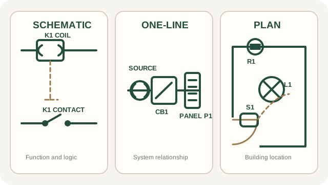
The same project can use all three drawing families. Each panel answers a different question, and each must be read with its own legend, tags, notes and schedules.
- [relay]()
- [contactor]()
- [transformer]()
- [circuit breaker]()
- [fuse]()
- [motor]()
- [outlet]()
- [switch]()
- [GFCI receptacle]()
- [lamp]()
- [wire crossing]()
## Checklist: Which Electrical Drawing Sheet Do You Have?
Use this quick visual inspection before you match any icon in our schematic symbol families or floor plan legend guide:
1. Do you see walls, door swings, room names, and a graphic scale bar?
Yes: You are looking at an Architectural Electrical Floor Plan. Go to #floor-plan-legend-reading and look for plan-view icons like a circle with blades (outlet) or an S mark (switch).
2. Does a single heavy line represent an entire three-phase or multi-wire feeder with slash marks or notes for conductor count?
Yes: You are looking at a One-Line (Single-Line) Diagram. Expect high-level power distribution symbols such as transformer, circuit breaker, and ground connections rather than individual control wires.
3. Are circuits arranged in parallel horizontal rungs or vertical columns for clarity, with one device's coil and contacts separated across the page?
Yes: You are looking at an Elementary Schematic Diagram. Read it for sequence of operation using #schematic-symbol-families and #schematic-reading-practice.
4. Are devices drawn in their approximate panel locations with all terminals grouped inside each component box and numbered wires running from terminal to terminal?
Yes: You are looking at a Wiring (Connection) Diagram. Use it for physical termination, harness routing, and point-to-point continuity checks.
5. Does the sheet mix a high-level feeder path with an inset control detail?
Yes: You have a Composite or Riser/Control Sheet. Check the sub-detail title under each diagram block before interpreting the symbols inside that boundary.
Source: DOE-HDBK-1011 Electrical Science; UFC 3-501-01; teaching illustration; follow your project legend (Checked: 5 November 2026).
- [schematic symbol families]()
- [floor plan legend guide]()
- [outlet]()
- [switch]()
- [transformer]()
- [circuit breaker]()
- [ground]()
## General Legend and Title-Block Reading Order
Never guess a symbol from memory alone when a project set includes a legend sheet (often numbered E-001 or G-001). Follow this six-step reading order every time you open a new drawing package:
Source: US GPO style and federal CAD standards (UFC 3-501-01); OSHA 29 CFR 1910 Subpart S documentation context; teaching illustration; follow your project legend (Checked: 5 November 2026).
1. Read the Title Block First: Check the sheet title, drawing number, and discipline prefix (such as E for Electrical or I for Instrumentation) in the bottom-right corner to confirm whether the sheet is a plan, one-line, schematic, or wiring diagram.
2. Verify the Revision and Issue Status: Look at the revision table near the title block. Ensure your legend sheet and your working drawing sheet come from the same issue set so recently added symbol modifiers are not missed.
3. Locate the Governing Standard Note: Check the general notes for a statement naming the symbol standard used by the design office (for example, IEC 60617, ANSI/IEEE Std 315, or a facility-specific CAD standard).
4. Match the Exact Graphic plus Subscripts in the Project Legend: Compare both the base shape and any letters, shading, or dashed lines next to it. On a floor plan, a plain circle, a half-shaded circle, and a circle with GFI next to it represent different devices; see our GFCI symbol and outlet symbol guides.
5. Check the Abbreviation and Device Tag Schedule: Read the abbreviation list alongside the symbol chart. A push button, selector switch, limit switch, or emergency stop often relies on an adjacent tag (PB, HOA, LS, E-STOP) to complete its meaning.
6. Read Sheet-Specific Keyed Notes and Footnotes Last: Before tracing the circuit or counting devices, check numbered callouts (keynotes) on the exact sheet you are reading. Keynotes frequently override a generic legend symbol with mounting heights, enclosure types, or special wiring instructions.
- [GFCI symbol]()
- [outlet symbol]()
- [push button]()
- [selector switch]()
- [limit switch]()
- [emergency stop]()
## Schematic Symbol Families and Reference Designators
Elementary and schematic diagrams focus on how a circuit works rather than where parts sit in a room. Instead of trying to memorize a single wall-sized poster of every variation, group schematic symbols into functional families and learn what each family does in the current path.
Sources, grounds, and junctions: Follow energy from a battery symbol or transformer symbol, verify the return and bonding path at every ground symbol, and check each wire crossing symbol to see whether intersecting lines connect at a dot or pass without touching.
Protection and switching: Trace how a circuit is isolated or controlled through a fuse symbol or circuit breaker symbol, manual operators like a switch symbol, push button symbol, selector switch symbol, or emergency stop symbol, and mechanically tripped contacts shown by a limit switch symbol.
Coils, relays, and power switching: In control schematics, an electromechanical coil and its contacts are often drawn far apart. Cross-reference the coil and contact sets using the guide pages for the relay symbol and contactor symbol.
Passive parts, semiconductors, and loads: Identify circuit conditioning and work-producing parts with the resistor symbol, capacitor symbol, inductor symbol, and diode symbol, along with outputs such as a lamp symbol or motor symbol.
Reference-designator reminders: Next to each schematic graphic you will usually see a letter-number tag (such as R1, C2, S1, K1, F1, or M1). The letter identifies the component class, and the number separates specific devices on the sheet and bill of materials. Because letter conventions vary between IEC, IEEE, and company standards, always check the drawing set's title block or designator table before assuming what a prefix means.
Source: IEC 60617 Graphical Symbols for Diagrams (reference overview, https://www.iec.ch/), US DOE Handbook Electrical Science Volume 1 (DOE-HDBK-1011/1-92, https://www.standards.doe.gov/), and teaching illustration; follow your project legend.
- [battery symbol]()
- [transformer symbol]()
- [ground symbol]()
- [wire crossing symbol]()
- [fuse symbol]()
- [circuit breaker symbol]()
- [switch symbol]()
- [push button symbol]()
- [selector switch symbol]()
- [emergency stop symbol]()
- [limit switch symbol]()
- [relay symbol]()
- [contactor symbol]()
- [resistor symbol]()
- [capacitor symbol]()
- [inductor symbol]()
- [diode symbol]()
- [lamp symbol]()
- [motor symbol]()
## Short Schematic Circuit-Reading Practice
When reading an unfamiliar schematic rung or branch, trace from the supply rail through protective and control elements to the load, and then to the return path. Note every normal state (normally open vs. normally closed) before imagining any button being pressed.
Source: Teaching illustration; follow your project legend, and US DOE Handbook Engineering Symbology, Prints, and Drawings (DOE-HDBK-1016/1-93).
- [fuse symbol]()
- [emergency stop symbol]()
- [push button symbol]()
- [lamp symbol]()
- [relay symbol]()
- [ground symbol]()
- [wire crossing symbol]()
## Short Schematic Circuit-Reading Practice
In the rest (unactuated) state shown on the diagram, is indicator lamp HL1 energized?
No. Although fuse F1 is intact and normally closed button S1 passes continuity in its rest state, the series normally open push button S2 is open, interrupting the path to HL1 and coil K1.
## Short Schematic Circuit-Reading Practice
Why is there a solid dot where the branch to HL1 meets the line to K1, while the vertical feeder line crossing earlier has no dot?
Under common schematic conventions, a dot at a T-junction confirms an intentional electrical connection feeding both parallel loads, whereas two lines crossing without a dot cross on the paper only and do not connect electrically. Always verify the junction rule in your sheet notes.
## Reading Architectural Floor Plans and Room Legends
Architectural electrical plans (often called power plans or lighting plans) show a top-down view of walls, doors, and rooms. Because small plan icons must fit tightly beside walls and cabinetry, architectural symbols look very different from schematic symbols and rely heavily on local letter tags and notes.
Items (Five-step plan reading order):
1. Read the title block and sheet index: Confirm whether you are viewing a power plan, a lighting plan, a combined layout, or a demolition sheet, and note the drawing scale.
2. Scan the project symbol legend first: Locate the legend sheet (often near the front of the electrical set) to see the exact shapes used for standard receptacles, special-purpose outlets, wall switches, and ceiling fixtures on that project.
3. Check general notes and mounting-height notes: Look for text notes explaining mounting heights above finished floor (AFF), weather-resistant or wet-location abbreviations, and wiring method remarks.
4. Trace room devices and control legs: Inside each room, locate wall and floor symbols and follow any dashed or curved switch-leg lines connecting switches to the luminaires or split receptacles they control.
5. Follow homerun arrows and panel/circuit tags: Find the arrowed lines pointing away from device groups; their text tags typically identify the serving panelboard and circuit number so you can cross-check the panel schedule.
Items (What common plan marks can tell you):
Receptacles: Usually drawn as a circle with one, two, or three lines extending to the wall line, or modified with shading and letter tags. Check the outlet symbol guide to compare duplex, single, and floor receptacles, and review the GFCI symbol guide to see how ground-fault protection is marked by letters (GFI or GFCI) on floor plans.
Wall switches: Often shown as the letter S with numeric or letter subscripts (S3 for three-way, SD for dimmer, SO for occupancy sensor). See the switch symbol guide for how plan switch icons differ from schematic contact blades.
Lighting fixtures (luminaires): Circles, rectangles, or recessed-can shapes indicate fixture style and location, often paired with a fixture-schedule callout tag. Compare plan luminaire marks with schematic indicator graphics in the lamp symbol guide.
Panelboards, equipment connections, and homerun tags: Shaded or boxed rectangles along walls typically mark panelboards or disconnect switches, while ticked homerun arrows indicate how field wiring groups back to a circuit breaker symbol position on the one-line diagram or panel schedule.
Source: UFC 3-501-01 Electrical Engineering (Unified Facilities Criteria, https://www.wbdg.org/), US GPO Standard Electrical Symbols, OSHA GFCI educational materials (https://www.osha.gov/electrical), and teaching illustration; follow your project legend.
- [outlet symbol]()
- [GFCI symbol]()
- [switch symbol]()
- [lamp symbol]()
- [circuit breaker symbol]()
## Floor-Plan Reading Check
Use this sample room layout to practice separating placement icons, control lines, and circuit tags before consulting a project schedule.
Source: Teaching illustration; follow your project legend, and UFC 3-501-01 Electrical Engineering.
- [outlet symbol]()
- [GFCI symbol]()
- [switch symbol]()
- [lamp symbol]()
## Floor-Plan Reading Check
What does the dashed curved line between the S mark by the door and the center ceiling circle tell the reader?
On an architectural lighting plan, that dashed line is a switch-leg indicator showing which switch controls the ceiling luminaire; it shows control intent rather than the exact physical path of the cable or conduit in the ceiling.
## Floor-Plan Reading Check
How do you confirm the exact requirements for the counter receptacles marked GFCI and the ceiling fixture marked Type A?
Cross-reference the GFCI notation against the sheet legend and general notes, follow the LP-1 / Ckt 3 homerun tag to panel schedule LP-1, and look up Type A in the project luminaire (lighting fixture) schedule.
## Why Similar Marks Change Meaning Across Sheet Types
A major source of confusion in electrical reading is that basic geometric shapes—circles, parallel lines, rectangles, and arcs—are reused across different drawing families. Without checking context on the electrical drawing symbols hub first, a reader can easily mistake a plan-view fixture for a schematic component.
Circles with Internal or External Lines: On an architectural floor plan, a small circle with two parallel ticks touching a wall represents a duplex outlet, and a plain ceiling circle often marks a lamp or recessed luminaire. On a schematic or one-line diagram, a circle usually represents a rotating machine rotor (such as a motor), a meter, or a relay coil depending on the standard.
Parallel Lines: Two parallel strokes inside a schematic current path can denote a normally open contact belonging to a contactor or relay, or they can represent a fixed capacitor. On a floor plan, two parallel lines crossing a conduit run are usually tick marks indicating two conductors inside that raceway, while on a one-line diagram they may indicate a disconnecting plug or busway joint.
Rectangles and Boxes: In an IEC schematic, a plain rectangle in series with a circuit line is a resistor, whereas a rectangle with a line running lengthwise through it is a fuse. On a wiring diagram or floor plan, a rectangle is typically a physical junction box, pull box, panelboard enclosure, or terminal block.
Zigzags, Loops, and Coils: A series of half-loops in a power path represents an inductor or one winding of a transformer, while on older schematics a rectangular or curved coil may drive a relay. Always trace whether the symbol connects to a magnetic core, a mechanical linkage dashed line, or a simple two-terminal load path.
Triangles and Arrows: A triangle against a bar inside a control or electronics schematic indicates a diode, whereas a solid triangle on an architectural wall plan often denotes a data/communications jack or a special-purpose receptacle defined only in that project's legend.
When a mark still looks ambiguous after checking #drawing-family-checklist, follow the #legend-reading-order steps before assuming its function.
Source: IEC 60617 reference database; DOE-HDBK-1011 Electrical Science; teaching illustration; follow your project legend (Checked: 5 November 2026).
- [electrical drawing symbols]()
- [outlet]()
- [lamp]()
- [motor]()
- [relay]()
- [contactor]()
- [capacitor]()
- [resistor]()
- [fuse]()
- [inductor]()
- [transformer]()
- [diode]()
## Five Common Mistakes When Reading Electrical Symbols
Even experienced technicians make errors when moving quickly between architectural sets and equipment manuals. Watch out for these five common traps:
1. Reading a Floor Plan Switch Arc as Physical Conduit: The curved dashed or solid line between a wall switch and a ceiling lamp on a floor plan shows which fixture the switch controls, not the physical path the electrician must bend the conduit or pull the cable.
2. Assuming Schematic Contacts Are Shown Powered Up: By convention, schematics show every push button, limit switch, and relay contact in its de-energized, unactuated (shelf) state—with coils off, pressure at zero, and levers resting. Misreading normal state reverses NO (normally open) and NC (normally closed) logic.
3. Confusing Capacitor Plates with Contact Bars or Battery Cells: Fixed capacitor symbols, battery cell stacks, and North American NEMA normally open contactor contacts all use parallel lines. Always check line length ratios (long/short pairs for a battery), curved plates or polarity marks (for capacitors), and device reference tags (C1 vs BT1 vs K1/M1).
4. Ignoring Connection Dots at Wire Intersections: When two lines cross at a right angle on a schematic or wiring diagram, the presence or absence of a junction dot—or a bridge hop—determines whether the conductors are electrically spliced or merely passing over each other. Review our wire crossing symbol guide to verify both dot-junction and bridge conventions.
5. Treating One-Line Diagrams as Complete Point-to-Point Wiring Guides: A one-line diagram intentionally omits neutral returns, individual phase conductors, and control interlocking loops to keep the power overview readable. Never wire a panel directly from a one-line without consulting the companion schematic and wiring diagrams.
Source: DOE-HDBK-1011 Electrical Science; OSHA electrical safety training materials; IEC 60617 reference; teaching illustration; follow your project legend (Checked: 5 November 2026).
- [switch]()
- [lamp]()
- [push button]()
- [limit switch]()
- [relay]()
- [capacitor]()
- [battery]()
- [contactor]()
- [wire crossing symbol]()
## Combined Drawing-Type Reading Check
Test your ability to match a real-world task to the right drawing family and symbol convention before jumping into individual component pages.
Question: You are troubleshooting a motor control panel. You already understand the logical sequence of the start/stop circuit from the elementary schematic, and you know which feeder breaker supplies the cabinet from the one-line diagram. Now you need to find the exact physical terminal block number (X1:4) where the field wire from a remote emergency stop station lands inside the enclosure. Which drawing family should you open?
A) The architectural electrical floor plan (#floor-plan-legend-reading), because it shows the room where the emergency stop button is mounted on the column.
B) The wiring (connection) diagram (#drawing-types), because it groups terminals by physical component layout and maps point-to-point wire numbers and terminal strip designations.
C) The system one-line diagram (#drawing-types), because a single line summarizes every control and power conductor entering the cabinet.
Answer: B is correct. While the elementary schematic shows how the emergency stop contact interrupts coil current logically, and the floor plan shows where the button sits in the building, only the wiring (connection) diagram maps physical enclosure layout, terminal strip numbers, and point-to-point conductor terminations. The one-line diagram (C) omits individual control wires entirely.
Source: DOE-HDBK-1011 Electrical Science; teaching illustration; follow your project legend (Checked: 5 November 2026).
- [emergency stop]()
## Frequently Asked Questions About Electrical Drawing Symbols
Source: DOE Fundamentals Handbook: Electrical Science (DOE-HDBK-1011); IEC 60617 reference database; UFC 3-501-01; teaching illustration; follow your project legend (Checked: 5 November 2026).
- [outlet]()
- [motor]()
- [transformer]()
- [circuit breaker]()
- [fuse]()
- [relay]()
- [GFCI outlets]()
- [switches]()
- [lamps]()
## Frequently Asked Questions About Electrical Drawing Symbols
Why must I identify the drawing type before looking up a symbol?
Because electrical drafting reuses simple geometric shapes across different sheet families. A circle with lines can mean a wall outlet on an architectural floor plan, a motor or meter on a one-line diagram, or a control component on a schematic. Checking #drawing-types and #drawing-family-checklist first narrows your lookup to the right symbol family in seconds.
## Frequently Asked Questions About Electrical Drawing Symbols
What is the difference between a one-line diagram and an elementary schematic?
A one-line (single-line) diagram condenses a multi-phase power distribution path into a single line to show high-level system flow from a transformer through a circuit breaker or fuse to major loads. An elementary schematic draws every active circuit path and splits multi-part devices (like a relay coil and its contacts) into logical rungs so you can trace exactly how the control and power circuits operate step by step.
## Frequently Asked Questions About Electrical Drawing Symbols
How does an architectural electrical floor plan differ from a schematic?
An architectural floor plan (#floor-plan-legend-reading) is drawn to physical building scale showing walls, rooms, and the installed locations of receptacles, GFCI outlets, switches, and lamps. A schematic (#schematic-symbol-families) ignores physical room layout and scale completely, arranging symbols solely to show electrical current paths and circuit logic.
## Frequently Asked Questions About Electrical Drawing Symbols
What does a wiring diagram add that a schematic leaves out?
A wiring (connection) diagram shows the physical arrangement of components inside a panel or equipment frame, keeping all terminals of each device together in one outline. It adds terminal block numbers, wire labels, cable bundling, and physical routing details that a schematic intentionally scatters across functional rungs for logical clarity.
## Frequently Asked Questions About Electrical Drawing Symbols
I followed a bookmark from an older symbol overview page—where should I start?
If you arrive from older overview pages, you will land on the drawing-type overview (#drawing-type-first). Start by matching your sheet in #drawing-family-checklist, review the six-step #legend-reading-order, and then jump directly to #schematic-symbol-families for circuit diagrams or #floor-plan-legend-reading for building plans.
## Public Sources and Next Symbol Guides
Graphical symbols on real engineering prints vary by standard edition, discipline, and drafting office. Treat this overview as a study companion and always defer to the symbol legend, schedules, and general notes bound into your project drawing set.
Next symbol guides to explore: Continue to individual component lessons for the outlet symbol, GFCI symbol, switch symbol, lamp symbol, ground symbol, wire crossing symbol, fuse symbol, circuit breaker symbol, relay symbol, contactor symbol, push button symbol, selector switch symbol, limit switch symbol, emergency stop symbol, resistor symbol, capacitor symbol, inductor symbol, diode symbol, battery symbol, transformer symbol, and motor symbol.
Editorial source check date: 5 November 2026.
Source: IEC 60617 Graphical Symbols for Diagrams (reference, https://www.iec.ch/); US DOE Electrical Science Vol. 1 and Engineering Symbology, Prints, and Drawings (https://www.standards.doe.gov/); UFC 3-501-01 Electrical Engineering (https://www.wbdg.org/); US GPO Standard Electrical Symbols; OSHA electrical safety resources (https://www.osha.gov/electrical); and teaching illustration; follow your project legend.
- [outlet symbol]()
- [GFCI symbol]()
- [switch symbol]()
- [lamp symbol]()
- [ground symbol]()
- [wire crossing symbol]()
- [fuse symbol]()
- [circuit breaker symbol]()
- [relay symbol]()
- [contactor symbol]()
- [push button symbol]()
- [selector switch symbol]()
- [limit switch symbol]()
- [emergency stop symbol]()
- [resistor symbol]()
- [capacitor symbol]()
- [inductor symbol]()
- [diode symbol]()
- [battery symbol]()
- [transformer symbol]()
- [motor symbol]()
- [UFC 3-501-01 — electrical drawings, legends and one-line requirements]()
- [US Government Publishing Office — Standard Electrical Symbols]()
- [IEC 60617 — graphical symbols for diagrams]()
- [Content responsibility and review status]()