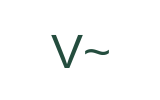
V~ · AC voltage
Volts with a wave mark. The selected function matters as well as the unit.
Electrician Jobsite English & Troubleshooting
Use a visual multimeter symbols chart to identify AC/DC voltage, resistance, continuity, diode, COM, range and CAT markings, with examples and safe reading boundaries.
A digital multimeter can place several functions, units and input labels around one dial. Read the selected function, active display indicator and lead jacks together. These teaching symbols are generic; the exact icon, dial position, button sequence and limits come from the manual for your meter.
Volts with a wave mark. The selected function matters as well as the unit.
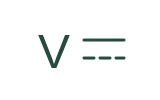
Volts with a solid line above a dashed line.
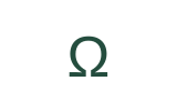
Ohms. This is a resistance function, not proof that a circuit is safe.
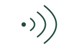
An audible continuity function; the exact icon and selection button vary by model.
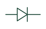
A separate function that may share a dial position with continuity.

An input label, not a measurement mode. Check the instrument manual for all jack assignments.
The continuity symbol commonly looks like sound waves. It selects a mode that checks for a conductive path and may beep below a model-specific resistance threshold. Confirm the active mode in the display and your meter's manual rather than relying only on the printing beside the dial.
This is a symbol-reading exercise, not an instruction to probe a live circuit. Resistance and continuity checks require a circuit made safe, including stored-energy controls where applicable.
An audible continuity function; the exact icon and selection button vary by model.
Ohms. This is a resistance function, not proof that a circuit is safe.
A separate function that may share a dial position with continuity.
A continuity beep reports a conductive path under the meter’s settings; OL often reports an open path or a value beyond the selected range. Neither result verifies absence of voltage or proves an installation safe.
On a simulated, isolated component, the meter shows 0.8 Ω and beeps. Which conclusion is supported? A: the path has low resistance under this setup. B: the whole installation is safe to touch. C: the component is certified for service.
A. The reading describes the tested path only. It does not verify absence of voltage, the wider installation, or the component's condition under load. If you chose B or C, separate the observation from the safety or serviceability claim and try again.
Useful wording: “The meter beeps in continuity mode.” “The display shows OL.” “The mode and threshold still need checking.” Avoid turning these observations into “It is safe.”
Editorial source check: 29 October 2026. Original teaching diagrams simplify the symbols; the manufacturer's manual controls the actual instrument. These materials do not certify electrical competence or replace supervised training.
A useful measurement report names the quantity, mode, range, test points, operating condition, reading, and unit. It also states whether the instrument, leads, and method were suitable for the environment.
Decide what to measure before choosing a function and connection. Voltage and continuity answer different questions.
Potential difference that changes polarity over time, measured using a suitable AC voltage function and method.
Example: The meter is set to AC voltage, and the reading is 119.6 volts between the specified test points.
Usage boundary: State the test points and operating condition, not only the number.
Potential difference with a defined polarity, measured using a suitable DC voltage function and method.
Example: The DC voltage reading is negative, so the lead polarity is opposite to the reference used.
Usage boundary: A negative sign is information, not automatically an instrument fault.
The rate of electric charge flow, reported in amperes or a submultiple such as milliamperes.
Example: Before measuring current, confirm the approved method, meter rating, function, and input connection.
Usage boundary: A wrong jack or method can create a dangerous low-impedance path.
Opposition to current flow, measured in ohms using the appropriate function on a circuit in the required safe state.
Example: Resistance mode must not be used on an energized circuit.
Usage boundary: Isolate, control stored energy, and verify the required condition before resistance testing.
A test function that indicates whether a sufficiently low-resistance path exists under the instrument's criteria.
Example: A continuity beep indicates a path under the meter's threshold; it does not describe the full circuit condition.
Usage boundary: Do not use continuity mode on an energized circuit.
The common input terminal normally used for the black test lead on a digital multimeter.
Example: The black lead is connected to COM, and the red lead position must match the selected function.
Usage boundary: Always follow the exact meter labeling and manual.
A socket on the meter for a test lead, assigned to specified measurement functions and limits.
Example: The red lead is in the current input jack, so stop before attempting a voltage measurement.
Usage boundary: Lead position and selected dial function must agree before contact.
The span of input values a meter function can display or measure in a selected or automatic setting.
Example: The meter is autoranging, but the selected function and rating still need confirmation.
Usage boundary: Autorange does not select the correct measurement category or safe method for you.
The smallest change in the measured quantity that the display can represent in a given range.
Example: Higher displayed resolution does not automatically mean higher accuracy.
Usage boundary: Do not report more certainty than the instrument specification and method support.
A safety classification related to the transient environment and intended measurement location of suitable test equipment.
Example: Confirm that the meter and leads have the appropriate category and voltage rating for the measurement location.
Usage boundary: A maximum voltage marking alone does not describe the complete safety suitability.
An authorized measurement has produced 23.8 volts DC between control terminals 5 and COM while the start command is active.
Report mode, points, operating state, value, unit, and what the reading does not prove.
With the meter set for DC voltage and the start command active, the reading between control terminal 5 and COM is 23.8 volts DC. This confirms the reading only at those points and under that state; it does not by itself confirm the condition of the contactor or the rest of the circuit.
Identify the requested tool and confirm the handover; possession does not authorize testing.
English communication and reasoning from supplied information; no instruction in live testing, qualification, or work authorization.
Maintained by Elect Learn. Independent licensed-electrician review has not been completed. Sources support general principles and do not imply endorsement.
Prerecorded synthetic English with slow playback, local-speech fallback, and a transcript. Choices receive feedback; expression uses checklist self-review, not automatic grammar grading.
Listen to a tool handover request, then check the illustration. It identifies the tool; it is not a connection or operation guide.
Please bring the digital multimeter to the training desk. Do not connect the leads to any equipment. We will confirm the exercise together.
Confirm the tool and destination in English, then ask what exercise is intended.
Digital multimeter
A digital multimeter was requested. The brief is collection for the training desk and explicitly prohibits connecting leads.
I will bring the digital multimeter to the training desk without connecting any leads. Can you confirm the exercise and the tool requirements with me first?
Transfer task: a different tool, still collection and confirmation only.
Bring the wire strippers to the practice bench. Do not start stripping any wire. We need to confirm the training material first.
Read back the collection task and ask which training material is intended.
Wire strippers
Wire strippers were requested. Collection does not include starting preparation or wiring.
I will bring the wire strippers to the practice bench and will not start stripping any wire. Can you confirm the training material and the required tool first?
Its meaning depends on the function and meter. It can indicate an over-range condition or an open path in resistance/continuity contexts. Check the specific manual before interpreting it.
No. A continuity indication usually means resistance is below the meter's defined threshold, not exactly zero and not proof of full circuit health.
No. Measurement requires task-specific training, a suitable instrument, manufacturer instructions, authorization, PPE and work controls, and supervised practical competence.
Copy this page's public material to ask an AI tool for terminology explanations, bilingual comparisons or revision questions. Keep the sources and safety limits in its answer, then check against this page.
Using this material, explain three key terms in English and Chinese, then give me one comprehension question. Keep the original sources, jurisdiction limits and stop-work conditions. Say when the material does not answer something. Do not provide live electrical work instructions.
Copies public content only, without your answers, report drafts or learning progress. Nothing is sent automatically to an AI service. AI can make mistakes; it cannot verify site safety or authorize work.
Maintained by Elect Learn · Page updated: · First published:
No independent professional review is recorded. Cited sources do not imply review or endorsement by those organizations. Sources and review policy
Page Markdown · Page JSON · AI content index
This site provides learning materials and does not replace local rules, permits, site procedures, or qualified judgment.