Electrician Jobsite English & Troubleshooting
Circuit Breaker Symbol: One-Line & Schematic Meaning
Read a circuit-breaker symbol in a one-line or schematic drawing, then confirm poles, trip function, ratings and protection type from the legend and device schedule.
Page highlights
- Read a circuit-breaker symbol in a one-line or schematic drawing, then confirm poles, trip function, ratings and protection type from the legend and device schedule.
- Original symbol illustrations, a reading check and feedback for learning.
What does this symbol mean?
Circuit Breaker Symbol
Represents a resettable switching device capable of making, carrying, and automatically breaking circuit currents under both normal operating conditions and abnormal fault conditions.
See the symbol
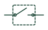
How to read it in context
- Distinguish the standards family: Look for the curved bridge between two terminal circles (common on North American one-line and power drawings) or an angled blade touching a stationary cross mark X (the IEC circuit breaker convention indicating fault-interrupting capability).
- Inspect the trip mechanism modifiers: Check for square or recessed-bracket thermal elements (overload sensing) and jagged, triangular, or coil-like magnetic elements (instantaneous short-circuit sensing) drawn along the breaker stem.
- Count poles and gang links: Follow dashed mechanical linkage lines across parallel phase conductors to see whether the breaker operates as a single-pole, two-pole, or three-pole common-trip assembly.
- Check drawout and auxiliary features: Look for double chevrons (>>) at both ends of the symbol indicating a drawout/racking breaker, and scan nearby control sheets for cross-referenced auxiliary contacts sharing the breaker tag (such as CB1 or Q1).
Common look-alikes and mistakes
- Switch Symbol (/guides/switch-symbol/): A basic isolating switch or disconnect has a plain straight blade without the curved breaker arc or the IEC X interrupt mark (often using a small perpendicular bar for a disconnector instead).
- Fuse Symbol (/guides/fuse-symbol/): A fuse is a non-resettable overcurrent device drawn as a rectangle with a line passing through it or an S-curve element, whereas a circuit breaker shows an openable contact mechanism.
- Contactor Symbol (/guides/contactor-symbol/): An IEC contactor uses a small half-circle arc on the fixed terminal post (or parallel bars in ladder diagrams) for frequent normal switching, while a circuit breaker uses an X mark for fault interruption.
Frequently asked question 1
Does the circuit breaker symbol tell me the trip current or interrupting capacity?
Check answer and feedback
No. The graphical symbol only identifies the device type and trip mechanism class; exact ampere ratings, trip curves, and fault ratings are listed in the panel schedule, one-line annotations, or bill of materials.
Frequently asked question 2
What do the double arrowheads on either side of a breaker symbol mean?
Check answer and feedback
Double chevrons pointing toward or away from the breaker contacts indicate a removable or drawout circuit breaker mounted in a switchgear cell rather than a fixed bolt-in unit.
Frequently asked question 3
Where can I compare this symbol with other power and control graphics?
Check answer and feedback
Readers arriving from older overview pages will land on the drawing-type overview (/guides/electrical-drawing-symbols/), where power, control, and plan symbols are grouped by context.
Standards, sources and related symbols
Editorial source check date: 5 November 2026. This reference explains standard circuit breaker graphics using public documentation (IEC 60617, DOE handbooks, UFC, and OSHA). The presence of a circuit breaker symbol on a drawing does not establish equipment interrupting ratings, arc-flash boundaries, coordination settings, or safe isolation status in the field. Always consult the project panel schedules, coordination study, and site lockout/tagout procedures.
These are independently drawn teaching diagrams. They help you read a drawing, but the project legend, applicable standard and equipment documentation control the actual meaning. Editorial source check: 5 November 2026.
- IEC 60617 — graphical symbols for diagrams
- Eaton — circuit breaker fundamentals
- IEC 60617
- DOE Fundamentals Handbook: Electrical Science
- US GPO — Standard Electrical Symbols
- UFC — Electrical Engineering
- Electrical Drawing Symbols: 4 Core Diagram Types
- Fuse Symbol in Electrical Drawings
- Switch Symbol in Electrical Schematics & Floor Plans
- Contactor Symbol: Coil, Main Contacts & Control
- Content responsibility and review status
AI study helper
Copy this page's public material to ask an AI tool for terminology explanations, bilingual comparisons or revision questions. Keep the sources and safety limits in its answer, then check against this page.
A study question to try
Using this material, explain three key terms in English and Chinese, then give me one comprehension question. Keep the original sources, jurisdiction limits and stop-work conditions. Say when the material does not answer something. Do not provide live electrical work instructions.
Copies public content only, without your answers, report drafts or learning progress. Nothing is sent automatically to an AI service. AI can make mistakes; it cannot verify site safety or authorize work.
Maintained by Elect Learn · Page updated: · First published:
No independent professional review is recorded. Cited sources do not imply review or endorsement by those organizations. Sources and review policy
Page Markdown · Page JSON · AI content index
This site provides learning materials and does not replace local rules, permits, site procedures, or qualified judgment.