Electrician Jobsite English & Troubleshooting
Fuse Symbol in Electrical Drawings
Learn how to read the fuse symbol in electrical schematics, compare IEC and ANSI styles, and distinguish fuses from resistors and circuit breakers.
Page highlights
- Learn how to read the fuse symbol in electrical schematics, compare IEC and ANSI styles, and distinguish fuses from resistors and circuit breakers.
- Original symbol illustrations, a reading check and feedback for learning.
What does this symbol mean?
Symbol Name: Fuse (Overcurrent Fusible Link)
Designator Letters: Commonly labeled F or FU on schematic diagrams (project standards vary).
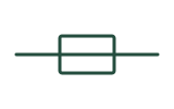
The fuse symbol represents a sacrificial overcurrent protection device containing a calibrated conductive link that melts and opens the circuit when current exceeds a design threshold for a specified duration.
See the symbol
How to read it in context
- Locate the symbol in series: Scan the power supply path, control transformer primary/secondary, or branch feed; a fuse is always drawn in series with the load it protects.
- Identify the regional drawing convention:
- IEC rectangle with pass-through line: Look for a rectangle where the circuit line runs straight through from one end to the other. This continuous inner line is the critical detail that separates it from a fixed resistor.
- ANSI/IEEE S-curve: Look for an S-shaped wave bridging two terminal points. This represents the physical fusible element inside a cartridge or plug fuse.
- Read the reference designator and notes: Check text adjacent to the symbol (such as FU1 or F2). Any amperage, time-delay characteristic, or interrupting class is specified in the bill of materials or next to the symbol by the project engineer—never assumed from the symbol's shape alone.
- Trace upstream and downstream: Identify the line side (source) and the load side to understand which downstream components lose power if the fuse opens.
- Verify on the project legend: Because some CAD libraries use plain rectangles or filled end-caps for special fuse types (like striker fuses), always confirm the exact graphic against the drawing set's symbol legend.
Common look-alikes and mistakes
- Fuse vs. resistor-symbol: In IEC-style drawings, both use a rectangular body. However, a standard resistor-symbol is an empty rectangle where the conductor lines stop at the outer edges, whereas the IEC fuse symbol has the conductor line drawn all the way through the center of the rectangle.
- Fuse vs. circuit-breaker-symbol: Both provide overcurrent protection in series with a circuit. A fuse is a one-time sacrificial element (drawn as a pass-through box or S-curve), while a circuit-breaker-symbol is a resettable switching device typically drawn with an arched contact, a hinged switch arm, or a thermal/magnetic actuator mark.
- Fuse vs. wire-crossing-symbol: Beginners sometimes confuse the curved ANSI fuse wave with the older "bridge/hop" style of a wire-crossing-symbol. A wire crossing jump always arches over another perpendicular line, while an ANSI fuse S-curve connects two inline terminals along a single path with no intersecting wire underneath.
Frequently asked question 1
Why are there two completely different shapes for the fuse symbol?
Check answer and feedback
Different standards organizations evolved distinct graphical habits. The S-curve between two terminals became common in North American (ANSI/IEEE) schematics, while the rectangle with a continuous center line is the standard graphical form in IEC 60617. Many modern industrial drawings use the rectangular style globally.
Frequently asked question 2
Does the fuse symbol tell me whether it is a fast-acting or time-delay fuse?
Check answer and feedback
Generally, the basic schematic symbol only indicates the presence of a fuse. Special variants exist in IEC 60617 (such as thickened ends or striker-pin lines), but exact clearing characteristics and ratings are normally stated in text notes or the component schedule rather than inferred from the graphic alone.
Frequently asked question 3
What do the letters F or FU next to the symbol mean?
Check answer and feedback
They are reference designators used to cross-reference the schematic symbol with the parts list, panel layout diagram, and physical wire labels. Always check your drawing set's legend to see which letter code the designer selected.
Frequently asked question 4
I came here from an older general symbols overview page; where do I find the rest of the schematic icons?
Check answer and feedback
Readers arriving from older overview pages will land on the drawing-type overview at electrical-drawing-symbols, which organizes individual symbols by function.
Standards, sources and related symbols
This page provides educational guidance on recognizing graphical symbols in electrical diagrams. It does not provide component sizing, overcurrent coordination calculations, voltage ratings, or safety certification rules. Graphic variations occur across CAD packages and local standards (such as IEC 60617, DOE educational handbooks, and UFC criteria); always treat the specific project legend and equipment documentation as the final authority.
These are independently drawn teaching diagrams. They help you read a drawing, but the project legend, applicable standard and equipment documentation control the actual meaning. Editorial source check: 5 November 2026.
- IEC 60617 — graphical symbols for diagrams
- Littelfuse Fuseology — fuse characteristics and selection factors
- IEC 60617
- DOE Fundamentals Handbook: Electrical Science
- US GPO — Standard Electrical Symbols
- UFC — Electrical Engineering
- Electrical Drawing Symbols: 4 Core Diagram Types
- Circuit Breaker Symbol: One-Line & Schematic Meaning
- Resistor Symbol: IEC Rectangle vs US Zigzag
- Wire Crossing vs Junction: Dot Rules on Schematics
- Transformer Symbol: Windings, Core Lines & Dot Convention
- Content responsibility and review status
AI study helper
Copy this page's public material to ask an AI tool for terminology explanations, bilingual comparisons or revision questions. Keep the sources and safety limits in its answer, then check against this page.
A study question to try
Using this material, explain three key terms in English and Chinese, then give me one comprehension question. Keep the original sources, jurisdiction limits and stop-work conditions. Say when the material does not answer something. Do not provide live electrical work instructions.
Copies public content only, without your answers, report drafts or learning progress. Nothing is sent automatically to an AI service. AI can make mistakes; it cannot verify site safety or authorize work.
Maintained by Elect Learn · Page updated: · First published:
No independent professional review is recorded. Cited sources do not imply review or endorsement by those organizations. Sources and review policy
Page Markdown · Page JSON · AI content index
This site provides learning materials and does not replace local rules, permits, site procedures, or qualified judgment.