Electrician Jobsite English & Troubleshooting
Transformer Symbol: Windings, Core Lines & Dot Convention
Recognize a transformer symbol, read winding, core, tap and polarity-dot details, and avoid inferring voltage ratio, isolation or ratings from the icon alone.
Page highlights
- Recognize a transformer symbol, read winding, core, tap and polarity-dot details, and avoid inferring voltage ratio, isolation or ratings from the icon alone.
- Original symbol illustrations, a reading check and feedback for learning.
What does this symbol mean?
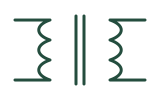
A transformer symbol commonly shows two windings facing each other. Parallel lines between them can denote a magnetic core; an air-core or other transformer may use a different convention. The symbol represents magnetic coupling, not the physical shape of the component.
Dots, taps and winding labels can show polarity relationships or connection points. They do not by themselves provide the turns ratio, voltage, power, frequency, insulation class or suitability for a particular circuit.
See the symbol
How to read it in context
- Find the reference designator—often T or TX—and match every winding terminal to the drawing labels.
- Check for a core mark, polarity dots, centre taps, shield connections or multiple secondary windings.
- Use the bill of materials, transformer schedule and manufacturer datasheet for ratio, ratings, isolation and terminal identification.
Common look-alikes and mistakes
- Two coupled coils can represent a transformer, current transformer, potential transformer or another magnetic component; the symbol variant and labels matter.
- A pair of core lines does not prove galvanic isolation or a particular insulation rating.
- A polarity dot describes the referenced instantaneous winding relationship; it is not a permanent positive or negative terminal mark.
Try the symbol-reading check
A transformer drawing shows a dot beside the top terminal of each winding. What does that support?
Check answer and feedback
It supports a referenced polarity relationship between those winding terminals under the drawing convention. It does not state the turns ratio, rated voltage, power, isolation class or a safe connection method.
Standards, sources and related symbols
These are independently drawn teaching diagrams. They help you read a drawing, but the project legend, applicable standard and equipment documentation control the actual meaning. Editorial source check: 28 October 2026.
AI study helper
Copy this page's public material to ask an AI tool for terminology explanations, bilingual comparisons or revision questions. Keep the sources and safety limits in its answer, then check against this page.
A study question to try
Using this material, explain three key terms in English and Chinese, then give me one comprehension question. Keep the original sources, jurisdiction limits and stop-work conditions. Say when the material does not answer something. Do not provide live electrical work instructions.
Copies public content only, without your answers, report drafts or learning progress. Nothing is sent automatically to an AI service. AI can make mistakes; it cannot verify site safety or authorize work.
Maintained by Elect Learn · Page updated: · First published:
No independent professional review is recorded. Cited sources do not imply review or endorsement by those organizations. Sources and review policy
Page Markdown · Page JSON · AI content index
This site provides learning materials and does not replace local rules, permits, site procedures, or qualified judgment.