Electrician Jobsite English & Troubleshooting
Switch Symbol (Schematic & Plan Views)
Learn how to identify the basic electrical switch symbol in circuit schematics (NO/NC contacts) and architectural floor plans, and distinguish it from push buttons and relays.
Page highlights
- Learn how to identify the basic electrical switch symbol in circuit schematics (NO/NC contacts) and architectural floor plans, and distinguish it from push buttons and relays.
- Original symbol illustrations, a reading check and feedback for learning.
What does this symbol mean?
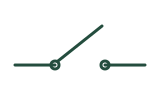
This graphic is called a switch symbol, disconnecting switch contact, or single-pole switch symbol. In circuit schematics and ladder diagrams, it represents a manually operated mechanical contact (such as SPST—Single-Pole Single-Throw), while on architectural floor plans it represents a wall-mounted lighting or appliance control switch.
The switch symbol indicates a manually controlled point in a circuit that opens to interrupt current flow or closes to complete the path.
See the symbol
How to read it in context
- Identify the drawing type first: Check whether you are reading a circuit schematic (which shows internal electrical contacts and blades) or an architectural floor plan (which shows a letter S or flagged circle on a wall).
- Check the rest state (NO vs. NC) on schematics: By drafting convention, schematic switches are drawn in their unactuated (normal/shelf) state. If the blade is separated from the terminal, it is Normally Open (NO); if the blade touches across the terminal, it is Normally Closed (NC).
- Count poles and throws: Look for dashed mechanical linkage lines connecting multiple switch blades (multi-pole) or extra stationary contact points that allow the blade to flip between two paths (double-throw).
- Inspect the actuator mark on the blade: A plain hinged line represents a basic toggle or knife switch. Special shapes attached to the blade indicate specific actuators (such as rotary selectors, push buttons, or mechanical limit cams).
- Read subscripts on architectural plans: Next to a plan-view S, check for modifiers like S3 (three-way switch), S4 (four-way switch), or SD (dimmer), and verify each suffix in the project symbol legend.
Common look-alikes and mistakes
- Push Button Switches (push-button-symbol): A push button also opens or closes contacts, but its symbol typically uses a T-shaped plunger bar bridging two contacts (or an actuator button icon on an IEC contact blade) to show momentary spring-return action rather than a maintained toggle blade.
- Selector Switches (selector-switch-symbol): A selector switch adds rotary position marks, arrows, or a target table to the contact symbol to show multiple maintained or momentary positions.
- Limit Switches (limit-switch-symbol): Limit switches share the same base NO/NC blade geometry as a standard switch, but add a small wedge or cam roller mark on the blade to show mechanical actuation by machine travel.
- Relay and Contactor Contacts (relay-symbol and contactor-symbol): In ladder logic and IEC schematics, automated relay contacts look very similar to manual switch blades or parallel bars, but lack a manual handle mark and are tied by reference designators (such as K1 or CR1) to an electromagnetic coil elsewhere on the sheet.
Frequently asked question 1
Are switches drawn in the "on" or "off" position on electrical schematics?
Check answer and feedback
Electrical schematics show switches in their normal, unactuated (de-energized or shelf) position. For a standard normally open (NO) switch, that means it is drawn open ("off").
Frequently asked question 2
Why does a floor plan use the letter "S" while a wiring diagram uses an angled line?
Check answer and feedback
Floor plans only need to show the installer where to mount the switch box on the wall and which fixtures it controls. Schematics and wiring diagrams must show how the electrical contacts actually break or make the circuit path.
Frequently asked question 3
What does a dashed line between two switch blades mean?
Check answer and feedback
A dashed line connecting two or more switch blades indicates a mechanical linkage—meaning both poles move together simultaneously when operated by a single handle.
Frequently asked question 4
Where can I see how plan symbols and schematic symbols fit into different drawing types?
Check answer and feedback
Readers arriving from older overview pages will land on the drawing-type overview at electrical-drawing-symbols, which explains the difference between architectural layout plans and schematic diagrams.
Standards, sources and related symbols
Switch contact graphics differ between IEC 60617, North American industrial ladder diagrams, and architectural plan standards (such as US GPO and UFC symbol sets). Always check the project legend and drawing notes to confirm contact states, pole arrangements, and plan-view letter subscripts.
These are independently drawn teaching diagrams. They help you read a drawing, but the project legend, applicable standard and equipment documentation control the actual meaning. Editorial source check: 5 November 2026.
- IEC 60617 — graphical symbols for diagrams
- US Government Publishing Office — Standard Electrical Symbols
- IEC 60617
- DOE Fundamentals Handbook: Electrical Science
- US GPO — Standard Electrical Symbols
- UFC — Electrical Engineering
- Electrical Drawing Symbols: 4 Core Diagram Types
- Push Button Symbol: NO, NC & Momentary Contacts
- Selector Switch Symbol: Positions & Contacts
- Limit Switch Symbol: Actuator & Contacts
- Outlet Symbol (Receptacle) in Electrical Drawings
- Content responsibility and review status
AI study helper
Copy this page's public material to ask an AI tool for terminology explanations, bilingual comparisons or revision questions. Keep the sources and safety limits in its answer, then check against this page.
A study question to try
Using this material, explain three key terms in English and Chinese, then give me one comprehension question. Keep the original sources, jurisdiction limits and stop-work conditions. Say when the material does not answer something. Do not provide live electrical work instructions.
Copies public content only, without your answers, report drafts or learning progress. Nothing is sent automatically to an AI service. AI can make mistakes; it cannot verify site safety or authorize work.
Maintained by Elect Learn · Page updated: · First published:
No independent professional review is recorded. Cited sources do not imply review or endorsement by those organizations. Sources and review policy
Page Markdown · Page JSON · AI content index
This site provides learning materials and does not replace local rules, permits, site procedures, or qualified judgment.