Electrician Jobsite English & Troubleshooting
Relay Symbol: Reading Coils, Contacts, and Shared Reference Tags
Learn how to read a relay symbol on electrical schematics. Understand how a shared tag links the relay coil to its NO and NC contacts, and how it differs from contactors and switches.
Page highlights
- Learn how to read a relay symbol on electrical schematics. Understand how a shared tag links the relay coil to its NO and NC contacts, and how it differs from contactors and switches.
- Original symbol illustrations, a reading check and feedback for learning.
What does this symbol mean?
Term: Relay Symbol (Control Relay / Electromechanical Relay)
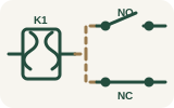
Represents an electrically operated switching device where energizing a control coil opens or closes one or more separate circuit contacts linked across the schematic by a shared reference tag.
See the symbol
How to read it in context
- Locate the relay coil: Look for a circle, rectangle, or parenthesis-style coil symbol in the control circuit path. Note its reference designation (for example, K1 or CR1).
- Trace the shared reference tag: Search the rest of the schematic—often on different rungs or sheets—for contact symbols bearing the exact same tag (K1 or CR1). The shared tag is what proves the coil and contacts belong to the same physical device.
- Identify the shelf (unpowered) contact states: Distinguish between Normally Open (NO) contacts (parallel lines or an open gate that closes when the coil is energized) and Normally Closed (NC) contacts (parallel lines with a diagonal slash or closed gate that opens when the coil is energized).
- Check cross-reference numbers: Many ladder diagrams list line numbers or sheet coordinates next to the coil to tell you exactly where its associated contacts are drawn.
- Verify ratings in the equipment schedule: Remember that the graphic symbol alone does not prove coil voltage, contact current rating, time-delay behavior, or the live energized state in the field. Always consult the bill of materials and project legend.
Common look-alikes and mistakes
- Relay vs. Contactor (contactor-symbol): On many schematics, both use identical or nearly identical coil and contact graphics. They are distinguished primarily by their reference tag letters (such as CR or K for control relays versus M or C for power contactors) and their circuit role, where contactors switch heavier power loads like a motor-symbol circuit.
- Relay Contact vs. Manual Switch (switch-symbol): A single-pole switch and a relay contact both control circuit continuity, but manual switches include an actuator line or toggle feature operated by hand, whereas relay contacts are drawn as parallel bars or basic contact points driven remotely by a tagged coil.
- Relay Contact vs. Push Button (push-button-symbol): Push buttons display a T-shaped plunger actuator showing momentary or maintained manual operation; relay contacts lack manual actuators and depend entirely on their linked coil state.
- Relay Coil vs. Inductor (inductor-symbol): Older or regional standards sometimes draw a relay coil as a series of loops resembling a passive inductor. Check the reference tag (K or CR versus L for inductor) and look for associated switching contacts elsewhere on the drawing.
Frequently asked question 1
Why are the relay coil and its contacts drawn in different places on a schematic?
Check answer and feedback
Schematics separate the coil and contacts by function to keep circuit paths clear. The coil is placed in the control logic path, while its contacts are placed directly in the load or interlocking paths they control. The shared reference tag connects them logically.
Frequently asked question 2
Does the relay symbol tell me the coil voltage or contact amperage rating?
Check answer and feedback
No. The graphic symbol only indicates the functional relationship between a coil and its contacts. It does not prove coil voltage (AC or DC), contact rating, or enclosure type. You must read the component schedule, title block notes, or part number list for ratings.
Frequently asked question 3
Does a Normally Open (NO) contact symbol mean the circuit is open right now in the equipment?
Check answer and feedback
No. Standard schematics show components in their de-energized, "shelf" state. A symbol on a drawing cannot prove the live field state of a circuit; always follow proper workplace safety and verification procedures before touching equipment.
Frequently asked question 4
I followed an older bookmark and landed on a general overview page—where are the rest of the control symbols?
Check answer and feedback
Readers arriving from older overview pages will land on the drawing-type overview at electrical-drawing-symbols, where you can navigate directly to individual control, power, and protection symbol guides.
Standards, sources and related symbols
Boundary Statement: Symbol shapes vary between IEC 60617, ANSI/IEEE, and project-specific CAD libraries. This guide provides general educational rules for reading detached coils and contacts; it does not establish electrical ratings, wiring clearances, or safety certifications. Always defer to the specific legend, notes, and schedules on your project drawing set.
These are independently drawn teaching diagrams. They help you read a drawing, but the project legend, applicable standard and equipment documentation control the actual meaning. Editorial source check: 5 November 2026.
- IEC 60617 — graphical symbols for diagrams
- US Government Publishing Office — relay symbols and control diagrams
- IEC 60617
- DOE Fundamentals Handbook: Electrical Science
- US GPO — Standard Electrical Symbols
- UFC — Electrical Engineering
- Electrical Drawing Symbols: 4 Core Diagram Types
- Contactor Symbol: Coil, Main Contacts & Control
- Switch Symbol in Electrical Schematics & Floor Plans
- Motor Symbol: Schematics, One-Line Diagrams & Ratings
- Push Button Symbol: NO, NC & Momentary Contacts
- Inductor Symbol: Coil, Core Lines & Variants
- Content responsibility and review status
AI study helper
Copy this page's public material to ask an AI tool for terminology explanations, bilingual comparisons or revision questions. Keep the sources and safety limits in its answer, then check against this page.
A study question to try
Using this material, explain three key terms in English and Chinese, then give me one comprehension question. Keep the original sources, jurisdiction limits and stop-work conditions. Say when the material does not answer something. Do not provide live electrical work instructions.
Copies public content only, without your answers, report drafts or learning progress. Nothing is sent automatically to an AI service. AI can make mistakes; it cannot verify site safety or authorize work.
Maintained by Elect Learn · Page updated: · First published:
No independent professional review is recorded. Cited sources do not imply review or endorsement by those organizations. Sources and review policy
Page Markdown · Page JSON · AI content index
This site provides learning materials and does not replace local rules, permits, site procedures, or qualified judgment.